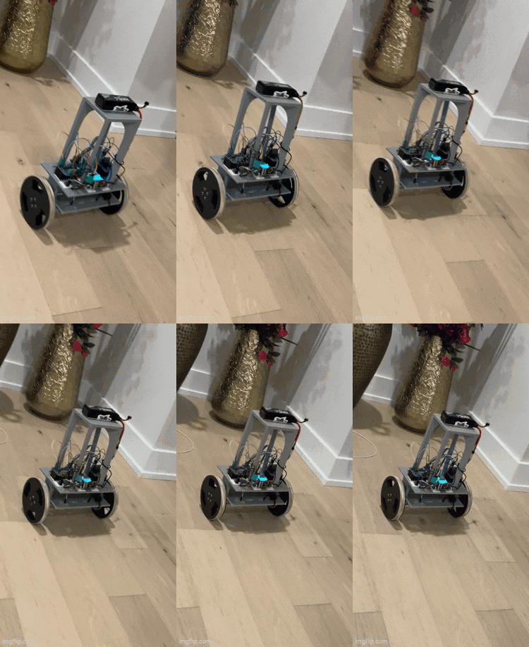
Self Balancing Robot
Monday, August 25, 2025


Software
Electronics
- ESP-wroom-32 Dev Board
- BNO085 IMU
- 2 FIT0186 Brushed DC Motors
- 3S Li-Po battery
- 12V Buck-Boost Converter with Voltage monitor Module


- 2 BTS7960 35A H-Bridge DC motor drivers
- N7803-1PH 3.3V Buck Converter
- XT-60 Connectors
- Electrical switch
Mechanical Parts
- 3D printed wheels and chassis designed in SolidWorks and printed on a Bambu Lab printer


- A 3D printed screw-hole IMU mount for stability

- Screw hole mounts for mounting the motors

- Top extension pieces for raising the centre of gravity for easier stability
- Flange Shaft Couplings for strong wheel connections
Firmware + Hardware Technical Details
- The BNO085 IMU communicates with the ESP-wroom-32 chip via the SPI communication protocol. A driver was created allowing for the connection.
- Bluetooth communication was also established to allow for real-time adjustment of gain factors
- Multi-threading, possible via the use of FreeRTOS
- A 4x quadrature encoder state machine which runs on separate threads allowing us to obtain odometry information
- The 3.3v Buck converter provides power to the microcontroller and IMU, and powers the logic of the motor controllers
Control Theory
This Self balancing robot was made based on the inverse pendulum theory. Taking advantage of the IMUs internal sensor fusion, a quaternion is obtained, which is then converted to the Euler angles, yaw, pitch, and roll.
In the case of this robot, pitch aligned with the rotation axis of the robot. For self-balancing, the goal was to keep the pitch angle at 0 degrees.
How this is achieved
Whatever direction the robot is falling towards, its motors must drive it towards that direction. This is because the goal is to keep the robot’s centre of mass, at the centre of the robot. This can be visualized is the robot ‘chasing’ its own centre of mass.
In order to maintain the pitch at exactly 0 degrees, the direction the robot is falling is determined, and based on that, the direction in which to drive the robot is determined. The speed at which the motors will drive the robot is then determined through a PID loop.
PID
Our error can be defined as the target angle subtracted by the current pitch angle. The goal is to reduce the error as much as possible by responding to the error in three separate way, the proportional, derivative, and integral responses
Proportional: The proportional response is a response that is proportional to the error, multiplied by the proportional gain factor.
Derivative: The derivative term, is based on the rate of change, or the velocity of the error. The derivative term plays a role both when the velocity of error is increasing and when it is decreasing. It opposes the rapid changes in error, creating a damping effect. Although it does not directly remove steady state error, it creates a smoothing effect, which is crucial for the self-balancing robot.
Integral: The integral term corrects for steady state error. It increases in magnitude the longer the system remains in error. It is therefore very useful for correcting small errors that the P term fails to correct
